
In addition to the IADC Classification system, the IADC (International Association of Drilling Contractors) developed an eight-point dull grading system to enable drillers and bit manufacturers to evaluate a drill bit’s performance. This eight-point system is described below and is used to assess bit damage on both tricones and fixed cutter bits. It does not apply to drag bits.
Mastering the art of dull grading according to IADC standards is crucial. It allows engineers and sales personnel to communicate effectively and determine whether a drill bit suits the intended application or if an alternative is necessary.

1. Inner Cutting Structure – Inner cutting structure wear is also noted by a number ranging from 0 to 8, with 0 being no wear and 8 being total wear.
2. Outer Cutting Structure—Wear in the outer cutting structure is also denoted by a number ranging from 0 to 8, with 0 being no wear and 8 being total wear.
Steel Tooth Bits
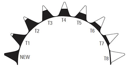
A measure of lost tooth height due to abrasion and/or damage.
0 – No loss of tooth height
8 – Total loss of tooth height
Button Bits
A measure of total cutting structure reduction due to lost, worn, and/or broken inserts. This includes button bits with either conical or chisel inserts.
0 – No lost, worn, and/or broken inserts
8 – All inserts lost, worn, and/or broken
Cutting Structure Wear
3. IADC Dull Grading Characteristics – Dull characteristics enables the bit salesperson or driller to determine the overall, distinctive aspect of the dulled drill bit according to IADC standards as follows:
BT – Broken Teeth
BU – Balled Up
CC – Cracked Cone
CD – Cone Drag
CI – Cone Interference
CR – Cored
CT – Chipped Teeth
ER – Erosion
FC – Flat Crested Wear
HC – Heat Checking
JD – Junk Damage
LC – Lost Cone
LN – Lost Nozzle
LT – Lost Teeth
NO – No Dull Characteristics
NR – Not Rerunnable
OC – Off Center Wear
PB – Pinched Bit
PN – Plugged Nozzle/Flow Passage
RG – Rounded Gauge
RR – Rerunnable
SD – Shirttail Damage
SS – Self-Sharpening Wear
TR – Tracking
WO – Wash Out
WT – Worn Teeth
4. Location – Location describes where the damage is on the cone.
N – Nose Row
M – Middle Row
G – Gauge Row
A – All Rows
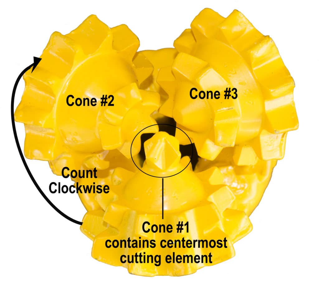
Cone Number One contains the centermost cutting component. Cones two and three follow in a clockwise manner.
- The nose row is the centermost cutting structure.
- The gauge row is the outermost cutting structure.
5. Bearings/Seals – For tricone drill bits designed as either open or roller bearing bits, bearing life is estimated on a scale of 0 to 8.
Non-Sealed Bearings
0 – No life used
8 – All life used,
i.e., no bearing life remaining
Sealed bearings
E – Seals effective
F – Seals failed
N – Not able to grade
“X” indicates fixed cutter.
6. Gauge – Gauge measures the amount of gauge wear a drill bit has suffered.
I- In Gauge
1 – 1/16” out of gauge
2 – 1/8” out of gauge
4 – 1/4” out of gauge
7. Other Dull Characteristics – Any other dull grading characteristics should be noted here using the codes from #3.
8. Reason Pulled – The following codes are used to indicate the reason a bit was pulled from the hole:
CM – Condition Mud
CP – Core Point
DMF – Downhole Motor Failure
DP – Drill Plug
DSF – Drill String Failure
DST – Drill Stem Test
DTF – Downhole Tool Failure
FM – Formation Change
HP – Hole Problems
HR – Hours on Bit
LIH – Left In Hole
LOG – Run Logs
PP – Pump Pressure
PR – Penetration Rate
RIG – Rig Repair
TD – Total Depth/Casing Depth
TQ – Torque
TW – Twist Off
WC – Weather Conditions
WO – Washout – Drill String