Atlas Copco
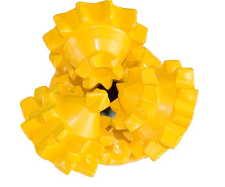
The Atlas Copco rotary drill bit product line
The Atlas Copco product line includes rotary drill bits designed to deliver competitive performance on current generation waterwell and oilfield drilling rigs.
Atlas Copco rotary drill bits are available in both open bearing and sealed bearing, and as milled tooth or tungsten carbide insert (TCI) bits.
Your selection will depend upon whether the application is Air or Mud circulation drilling.
See Atlas Copco products for water well and oilfield drilling here.
Key Applications
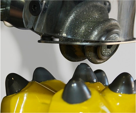
Blast Mining
Atlas Copco TCI bits have optimally designed bearing structures to withstand extreme pulldown loads typical of today's mining drill rigs.
Controlled metallurgy and generous air passages for cooling ensure extended bearing hours.
A robust bearing matched with an aggressive cutting structure provides good penetration rates in a wide cross section of formations.
Waterwell Drilling
Atlas Copco manufactures waterwell bits in milled tooth and tungsten carbide button bits in diameters from 2 1/2" up to 5 3/4" with center flush and jet flush available for both. The Focus division of Atlas Copco Secoroc offers larger diameter bits up to 12 1/4".
Product Features
Fast Penetration
A variety of insert shapes in the cutting structure design perform efficiently and increase the bit life.
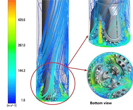
Optimized Nozzle Orientation
Efficient evacuation of cuttings through optimized nozzle size and orientation.
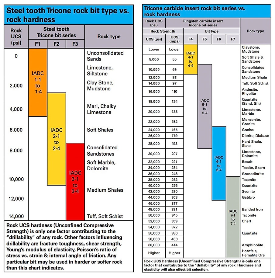
Drill Bit Selection Guide
Determine the drill bit type you need based on formation strength.
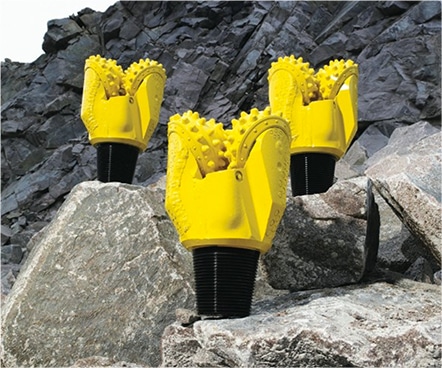
Rugged Shirttail Protection
Three different types of shirttail protection to fit your drilling needs:
- Regular protection for soft overburdens.
- Armor protection for wet and abrasive formations like sandstone.
- Enhanced protection for dense and fractured formations like iron ore.
Deeply set spherical inserts on shirttail for effective grip during long runs in abrasive formation. Hard metal welding for superior wear resistance.
TCI Cutting Structures
Atlas Copco manufactures Tungsten Carbide Insert (TCI) drilling bits in various cutting structure designs ranging from aggressive long conical inserts to moderately blunt compacts.
Four basic classifications for Tungsten Carbide Insert (TCI) drill bits conveniently divided into the F4, F5, F6, and F7 type series for easy identification. Each type is designed differently to tailor the cutting structure to most efficiently drill specific formations.
Widely spaced, large diameter chisel or conical inserts characterize the F4 series bits. This configuration promotes maximum penetration rates in softer formations that have a tendency to stick and ball up the cutting structure.

F4 Types
IADC: 4-1 to 4-4
Rock Strength/UCS: Very soft-soft, <10,000 psi / <83 mpa
Drilling RPM: 50 to 150 RPM
Weight on Bit: 1,000 to 4,000 (lbs/inch of bit diameter)
Super scoops, long conical inserts with sharp points are widely spaced for aggressive drilling and very high ROP at <100 m/hr typically used for coal overburden in formations like sandstone, siltstone, shale, limestone, alluvium, highliy altered volcanics and schists.

F5 Types
IADC: 5-1 to 5-4
Rock Strength/UCS: Soft-medium hard rock, 6,000-10,000 psi / 41-207 mpa
Drilling RPM: 50 to 150 RPM
Weight on Bit: 3,000 to 6,000 (lbs/inch of bit diameter)
Shorter and more closely spaced inserts in the F5 and F6 series promotes maximum penetration rates in hard formations.
Moderately spaced chisel and conical inserts with blunt points and medium protection for aggressive drilling and good penetration. Typically used for hard coal overburden in formations like volcanic rocks (rhyolite, dacite, andesite, etc.), Copper porhry, granite, diabase and “low grade” metamorphic rocks.

F6 Types
IADC: 6-1 to 6-4
Rock Strength/UCS: Medium hard rock, 24,000-44,000 psi / 166-303 mpa
Drilling RPM: 50 to 120 RPM
Weight on Bit: 4,000 to 7,000 (lbs/inch of bit diameter)
Shorter and more closely spaced inserts in the F5 and F6 series promotes maximum penetration rates in hard formations.
Closely spaced conical, ogive, and some chisel inserts with blunter points and shorter projections on an increased number of rows per cone. Typically used in formations like volcanic rocks (rhyolite, dacite, andesite, etc.), hard limestone, hard shale, quartzite, granodiorite, granote, diabase, diorite, skarn, tactite and medium grade metamorphic.

F7 Types
IADC: 7-1 to 7-4
Rock Strength/UCS: Hard rock, 38,000-60,000 psi / 262-400 mpa
Drilling RPM: 50 to 80 RPM
Weight on Bit: 5,000 to 9,000 (lbs/inch of bit diameter)
Densely packed, strong conical and ogive inserts with short projections. Typically used in formations like taconite, quartzite, banded iron formations and high grade metamorphic rocks like skarns, tacite, hornfels, etc.
Steel Tooth Cutting Structures
The F1, F2, and F3 Series divides the three basic classifications of steel tooth bits.
- The Type F1 steel tooth bit design performs optimally in formations of low compressive strength. Long slim, strong teeth designed for soft formation bits allow deep penetration in the formation with comparatively light weight on bit.
- The Type F2 steel tooth bit design performs best in medium formations and have more closely spaced teeth with more gage surface to resist wear.
- The Type F3 steel tooth design drills best in hard formations. These bits have higher capacity bearings and more closely spaced teeth with increased tooth angles to allow the use of heavier weights required to effectively drill hard formations.
Ideal conditions exist for milled tooth bits when drilling in very soft to medium hard rock. Tungsten carbide hard facing on the teeth give good wear resistance.
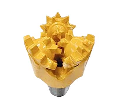
F1 Types
IADC: 1-1 to 1-4
Rock Strength/UCS: Less than 5,000 psi / <35 mpa
Weight on Bit: 1,000 to 4,000 (lbs/inch of bit diameter)
Large widely spaced teeth with interruptions, removals and deletions on gage. Full tooth hardfacing in both sealed and opened bearing configurations. Primary application - waterwell drilling.
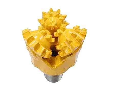
F2 Types
IADC: 2-1 to 2-4
Rock Strength/UCS: 3,000-10,000 psi / 20-79 mpa
Weight on Bit: 3,000 to 6,000 (lbs/inch of bit diameter)
More teeth and rows than F1 class bits. These bits have smaller and shorter teeth, with larger included angle for strength. Similar hardfacing to F1 class bits, except no hardfacing on lead side teeth. Available in sealed and open bearing configuration. Primary application - water well drilling.
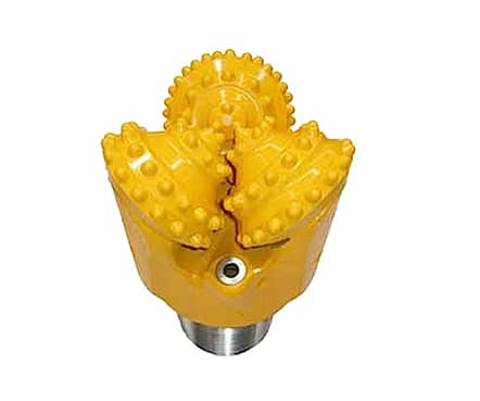
F3 Types
IADC: 3-1 to 3-4
Rock Strength/UCS: 8,000-14,000 psi / 55-100 mpa
Weight on Bit: 4,000 to 7,000 (lbs/inch of bit diameter)
Short, small closely spaced teeth for maximum bottom hole coverage. Tooth hardfacing only on gage and spear point. Maximum gage protection with optional carbide inserts. Available in sealed and open bearing configuration. Primary applications - waterwell and oilfield workover and completions.
Air Requirements
In rotary blasthole drilling, there is always a concern with delivery of air in sufficient volume and at the proper pressure to assure optimum bit performance when drilling with recommend bit weight and RPM.
Sufficient air volume should be provided to produce an annular return velocity of 5,000-7,000 ft./min. for light, dry materials; and 7,000-9,000 ft./min. for materials that are wet and/or heavy, and when drilling at penetration rates of 35m per hour or higher.
To determine volumetric requirements, the simple flow equation Q = AV may be used. Since friction losses in the annulus of relatively shallow holes of blasthole drilling are negligible, this becomes:
Q = V/183.35 (D2-d2)
The table on this page shows volumetric requirements in cubic feet of free air per minute necessary to provide both 5,000 and 7,.000 ft. per min. annular velocity for various possible combinations of hole size and drill pipe size.
The equation used is the simple flow equation: Q = AV.
With all constants combined and area expressed as difference between hole and pipe areas, this equation becomes:
Q = 27.27 (D2 - d2).
Q = cubic feet per minute free air necessary to obtain 5,000 feet per minute annular velocity
d = drill pipe outside diameter, inches
D = hole diameter, inches
Should Q be desired for some annular return velocity "V" other than 5,000 feet per minute, the result obtained above or from the table should be multiplied by the factor: V/5000.
Example: A 9 7/8" hole being drilled with 7 ¾" drill pipe at a desired annular velocity of 5,000 ft. per minute.
Solution:
Q = 27.27 [(9 7/8)2 - (7 ¾)2]
= 27.27 [97.52 • 60.06)
= 1022 cu. ft. per min. (shown in table)
Had 7,000 ft. per min. velocity been desired:
Q = (1022) 7000/6000 = 1431 cu. ft./min.
The above equation may also be rewritten to solve for annular velocity "V" when available compressor capacity, hole size and pipe size are known.
| Air Volume requirements for various hole diameter and drill pipe combinations for 5,000 ft. and 7,000 ft. per min. annular velocity. |
|||
| D hole diameter (in) | d drill pipe O.D. (in) | Q. - 5,000 Cu Ft/min free air | Q. - 7,000 Cu Ft/min free air |
| 4 1/2 | 2 7/8 3 1/2 4 | 327 218 116 | 458 305 162 |
| 4 3/4 | 2 7/8 3 1/2 4 | 390 282 178 | 546 395 249 |
| 5 1/8 | 2 7/8 3 1/2 4 | 491 382 280 | 687 535 392 |
| 5 1/8 | 2 7/8 3 1/2 4 | 491 382 280 | 687 535 392 |
| 5 1/8 | 2 7/8 3 1/2 4 | 491 382 280 | 687 535 392 |
| 5 1/8 | 2 7/8 3 1/2 4 | 491 382 280 | 687 535 392 |
| 5 1/8 | 2 7/8 3 1/2 4 | 491 382 280 | 687 535 392 |
| 5 1/8 | 2 7/8 3 1/2 4 | 491 382 280 | 687 535 392 |
| 5 1/8 | 2 7/8 3 1/2 4 | 491 382 280 | 687 535 392 |
| 5 1/8 | 2 7/8 3 1/2 4 | 491 382 280 | 687 535 392 |
| 5 1/8 | 2 7/8 3 1/2 4 | 491 382 280 | 687 535 392 |
| 5 1/8 | 2 7/8 3 1/2 4 | 491 382 280 | 687 535 392 |

